

Ready-to-Fly Drones · Shop by specification
Find the right ready-to-fly drones faster.
Choose the aircraft type and package format that matches how quickly you want to get flying.
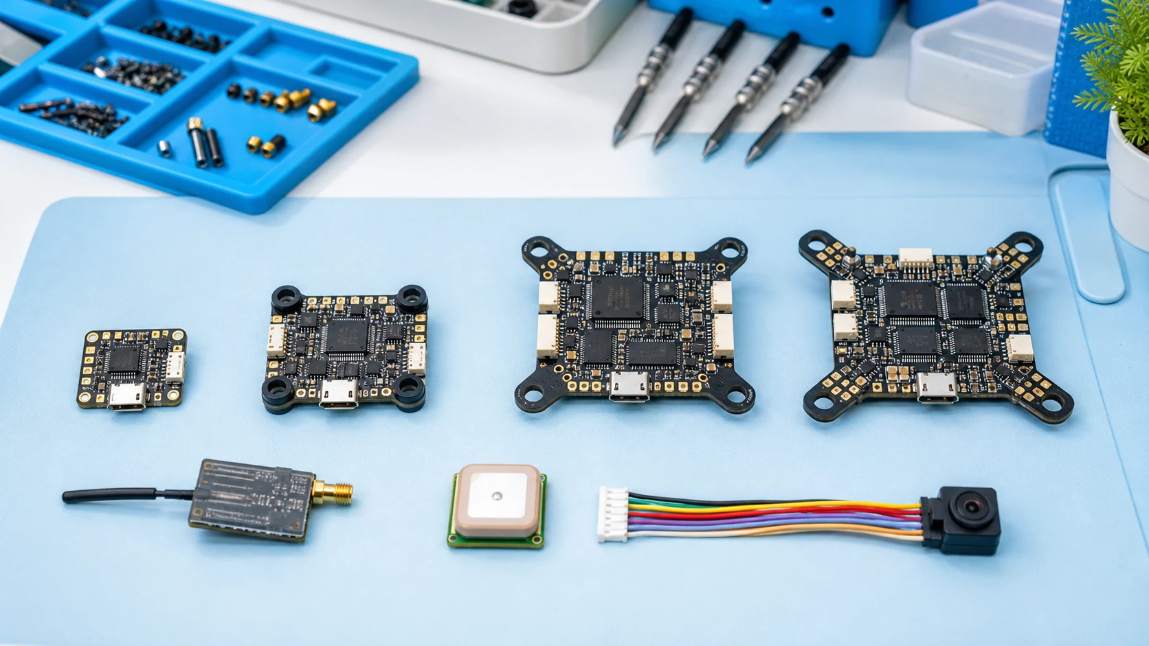
Choose an FPV flight controller by working backward from the build’s firmware, mounting, receiver, video system and peripheral needs. MCU and gyro names matter, but a board is useful only when its firmware target is maintained, its pinout fits the wiring plan, its power rails support the connected devices and its physical layout fits the frame.
Before comparing boards, list every device that must connect: ESC telemetry, receiver, video transmitter or digital video link, camera control, GPS, compass, barometer, buzzer, LEDs, current sensor and any extra servo or payload. Mark which devices need a full UART pair and which need only TX or RX. This prevents buying a feature-rich board that still lacks the usable pads or ports required by the build.
| System | Typical requirement to verify | Common conflict |
|---|---|---|
| Receiver | Supported serial protocol, voltage, UART RX and telemetry path | Wrong inversion, pad or receiver-provider setting |
| Digital video | Input voltage/current, UART, plug pinout and camera control | Connector fits but pin order or voltage is wrong |
| Analog video | Camera/VTX voltage, video in/out, OSD path and VTX control | Noise or bypassing the intended OSD route |
| GPS / compass | UART, optional I²C, voltage and firmware support | Using a UART already assigned to another device |
| ESC | Signal count, ground, current sensor, telemetry and plug pinout | Assuming FC and ESC connectors share a standard pin order |
The microcontroller runs the flight firmware and its features. F4, F7 and H7 families differ in processing capability, memory and peripheral resources, but board implementation and firmware support are equally important. Verify the exact MCU, the current firmware target, available flash storage and whether the features you need are supported together.
A faster MCU does not correct poor sensor placement, noisy power, incomplete firmware support or an unsuitable layout. For an existing build, staying with a well-supported target and known wiring can be more valuable than choosing the newest processor.
The gyro measures angular motion for the control loop. Check the exact sensor, bus implementation, firmware support and board orientation. Real performance also depends on power filtering, PCB layout, mechanical isolation, motor balance, frame resonance and software filters. Avoid claims that one gyro model guarantees smooth flight in every installation.
When replacing a board, save the old configuration and verify board alignment before arming. A physically rotated FC or a different sensor orientation can require an explicit alignment setting.
| Mechanical field | What to measure |
|---|---|
| Mounting pattern | Hole-to-hole dimensions and screw diameter |
| Board outline | Length, width and corner clearance inside the frame |
| Stack height | FC, ESC, gummies, spacers, plugs and wire bends |
| USB access | Connector side, camera/side-plate clearance and service access |
| Connector direction | ESC cable, digital-video plug and solder-pad access |
| Soft mounting | Correct grommets, compression and screw length |
Nominal 20×20 or 30.5×30.5 dimensions describe mounting centers, not the complete board envelope. Components, plugs and solder joints can extend beyond the hole pattern.
Record battery input range, regulated rail voltages, published current limits and which pads share each regulator. A 5 V pad and a 9/10 V video pad are not interchangeable. Add the current demand of the receiver, GPS, LEDs, camera and video transmitter, then keep margin for startup behavior and heat. Use a separate regulator when the board documentation requires it.
Never trust wire color or plug shape alone. Compare the FC and peripheral pinouts pin by pin. Re-pin a cable when necessary rather than applying the wrong voltage.
An all-in-one board can combine FC, ESC, receiver, OSD or video transmitter to save weight and space. The trade-off is repair scope: one failure can require replacing the complete board. A conventional stack is heavier and larger but can make component-level replacement easier. Choose the architecture around frame space, skill level, expected crash exposure and parts availability.
Browse FPV flight controllers, then match the ESC, radio receiver and video system. Continue through the 5-inch Freestyle build path or the Repair & Upgrade path. For an OEM match, send WXBMW the frame pattern, MCU target, ESC pinout, receiver, video system, GPS and required UARTs.
No. Processing headroom can help, but firmware support, layout, sensor implementation, power design and usable I/O determine whether the board fits the build.
No. Compare voltage, signal mapping, ground, current sensor, telemetry and connector pin order. Re-pin or wire directly only according to both manufacturers’ diagrams.
Count the exact devices and whether each needs TX, RX or both. A typical build may need resources for receiver, GPS, video control and telemetry, but the correct number depends on the complete I/O plan.
Use the old configuration as a reference, not a blind restore, unless the hardware target and revision are confirmed identical. Review resources, board alignment, ports and defaults.
Next step after this guide
Use the guide to define the required specifications, verify the aircraft-level Build path, then compare current WXBMW parts. Recheck voltage, mounting, protocol, connector and load compatibility before ordering.
No in-stock WXBMW option is shown for this exact category right now. Use the specification-match request instead of assuming a nearby item is compatible.
You must be logged in to post a comment.
No account yet?
Create an Account





One thought on “How to Choose an FPV Flight Controller: MCU, Gyro, Mounting and I/O”